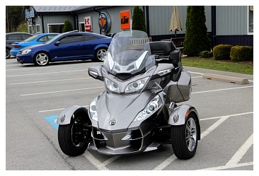
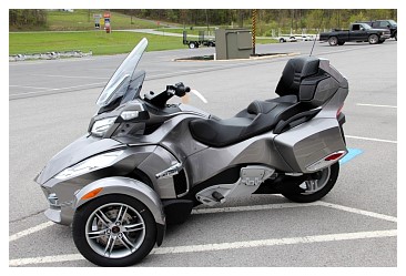
TomTom Rider 2
This GPS has been discontinued. Regardless, map updates are still available and it was considerably less for me to transfer this GPS from my Goldwing to my new Can-Am Spyder RT-S SM5.
SPECIAL THANKS TO NORTHSTAR (from SpyderLovers.com) FOR HIS ADVICE ON HOW TO MAKE THE POWER CONNECTION.
CLICK ON SMALLER IMAGES TO VIEW LARGER IMAGES.
 |
 |
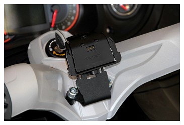
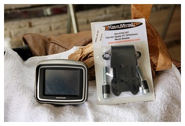 Mount Bracket from KewlMetal |
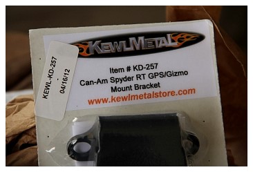 Mount Bracket from KewlMetal |
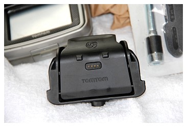 TomTom Rider 2 Mounting Bracket |
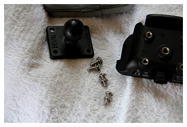 Ram Mount that was utilized to mount to my Goldwing |
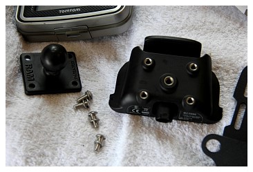 The Rider 2 Mount shares the same bolt hole configuration with most Garmin GPS |
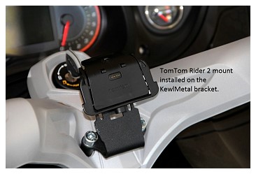
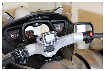
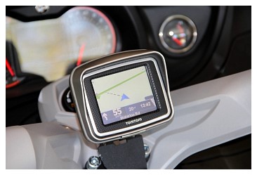
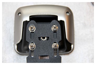 TomTom Rider 2 installed on Mount which is bolted to the KewlMetal Bracket |
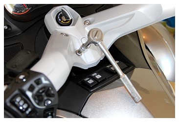 Removing bottom bolts from RT handlebars |
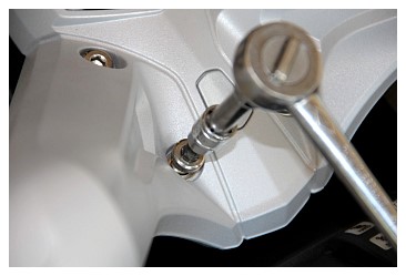 Removing bottom bolts from RT handlebars |
 Removing bottom bolts from RT handlebars |
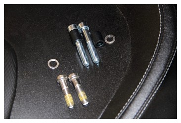 2 lower bolts are Spyder RT original bolts. Top bolts provided by KewlMetal |
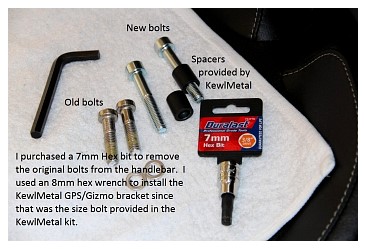 Original Spyder RT bolts are 7mm. I went to Autozone and purchased 7mm BIT. KewlMetal bolts are 8mm |
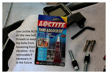 Use Loctite BLUE to dress the new bolts. Prevents the bolts from loosening from vibration. |
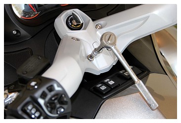
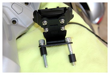
 KewlMetal Bracket and TomTom Rider 2 mounted to Spyder RT handlebars |
 KewlMetal Bracket and TomTom Rider 2 mounted to Spyder RT handlebars |
 KewlMetal Bracket and TomTom Rider 2 mounted to Spyder RT handlebars |
 KewlMetal Bracket and TomTom Rider 2 mounted to Spyder RT handlebars |
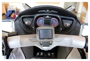 KewlMetal Bracket and TomTom Rider 2 mounted to Spyder RT handlebars |
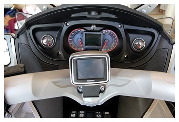 KewlMetal Bracket and TomTom Rider 2 mounted to Spyder RT handlebars |
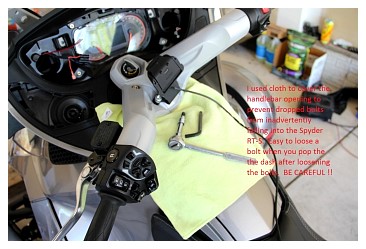 Remove the 4 bolts holding the dash in place. Pop the left speaker grill |
 Remove the 4 bolts holding the dash in place. Pop the left speaker grill |
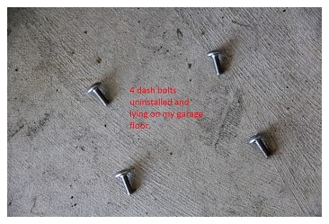 Dash Bolts Removed. Notice I placed a towel under the handlebars to prevent the bolts from falling into the motorcycle housing if the bolts are dropped. |
 Fuel Gauge |
 Temperature Gauge |
 |
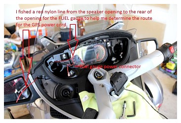
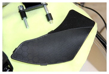 Left speaker grill popped out. I started at the top and worked around, releasing the tabs carefully |
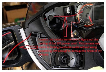 The RED nylon line was used by me to figure out the route I would take from the speaker opening to the back of the Fuel Gauge. I was trying to figure out the best way to route the power line. |
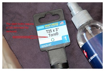 Purchased a T25 Torx screwdriver to remove the 4 Dash Screws |
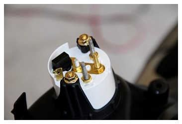
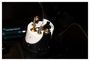
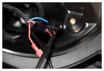
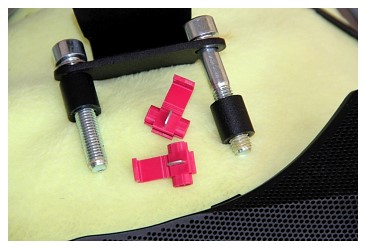 Purchased connectors for the power source. Chose to use orange and black wires from the fuel gauge as my power point for the TomTom Rider 2 GPS |
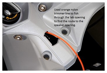 Used ORANGE nylon line to figure out how to route the power line from the GPS to the Speaker Opening |
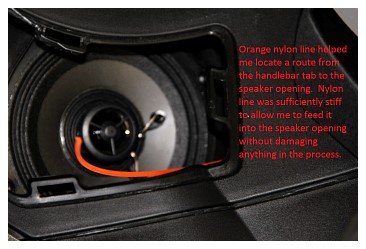 Used ORANGE nylon line to figure out how to route the power line from the GPS to the Speaker Opening |
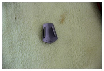 Center Tab. Pried it loose (beginning at the top) from the handlebar center console. Same opening that would be utilized by the OEM Garmin GPS from Can-Am |
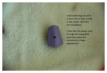 Used an electric soldering iron (with a fine point) to start a beginner hole for the power cord from the GPS through the tab. |
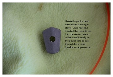 Heated a philips head screw driver (of sufficient diameter) on my gas stove. Then inserted the tip in the starter hole and widened the diameter of the opening so I could feed the power cord from the GPS through the tab in the center console. |
 After I fed the power cord through the tab, I reassembled the TomTom Rider 2 and KewlMetal Mounting Bracket on the the Spyder RT handlebar. I temporarily connected the power cord to make sure everything worked. |
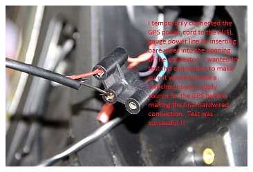 I fed the power cord into the speaker opening (ORANGE Nylon line photo above) and then up through the opening I discovered (see RED nylon line photo above) to the back of the opening for the FUEL gauge. Prior to making the final connections for the power, I tested the line and the power source by inserting the bare wires into the connector opening for the FUEL gauge |
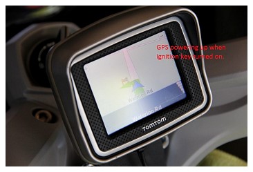 I turned the key on and the GPS powered up. |
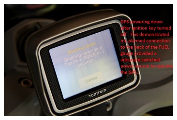 I turned the key off and the GPS begins to power down. |
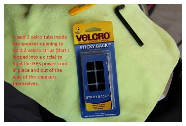 I used velcro strips and velcro tabs to hold the power cord wires in place. |